(0)
Products that you may be interested in
-

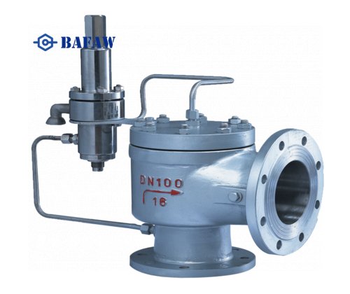
High Pressure Pilot Operated Relief Valve
-
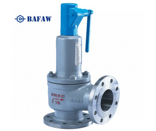
Steam Boiler Safety Valve
-
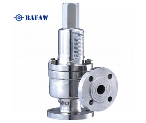
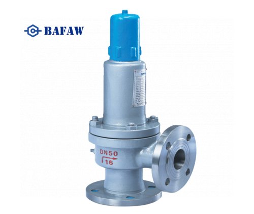
Stainless Steel Flanged Safety Relief Valve
-
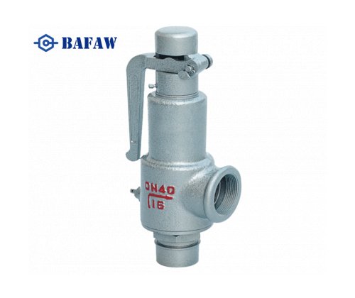
High Temperature Manual Release Steam Valve for Gas High Pressure
-
Closed Type Flanged End Spring Low Lift Safety Valve
-
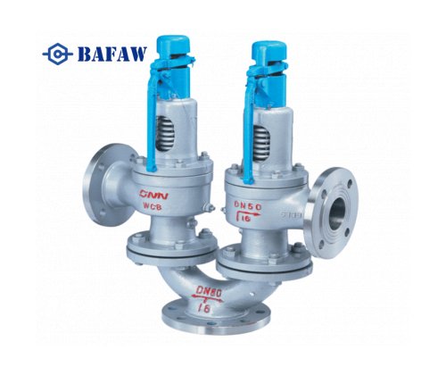
Y Type Double Spring Loaded Safety Valves
-
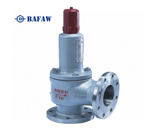
Spring Steam Boiler Pressure Relief Valve
-
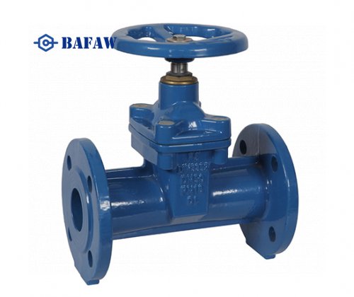
DIN3352 F5 Resilient Seat Cast iron Gate Valve
-
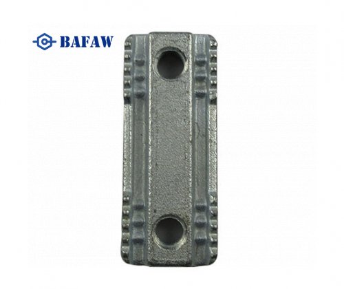
OEM Grey Iron And Ductile Iron Sand Casting Parts
-
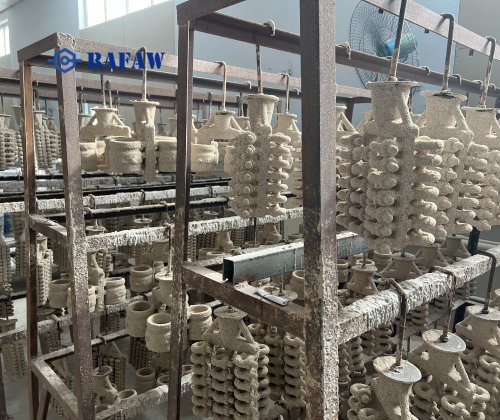
OEM Carbon Steel Precision Casting Part
-
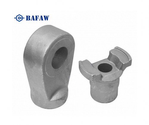
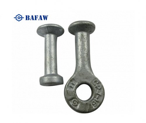
Ring Clutch - Precasting Concrete Lifting Ring Clutch
-
Lifting clutch
-
Double Clamp Nut
-
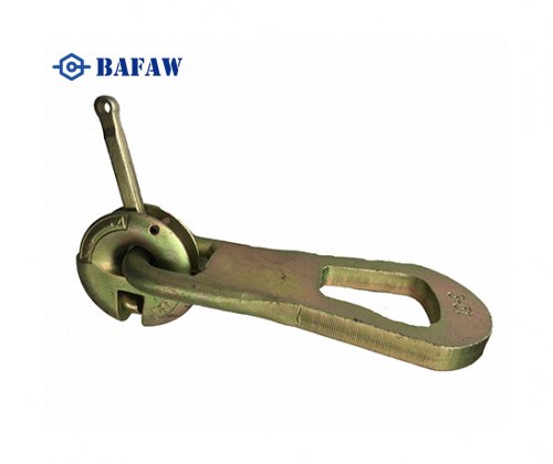
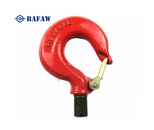
Carbon steel & Stainless steel Forging Metal Hook
-
OEM High Quality Forging Parts With Clevis End Fitting
-
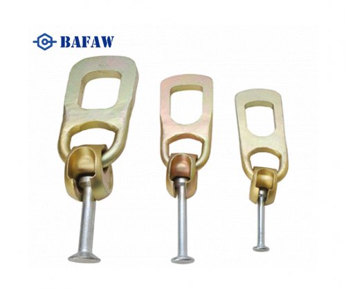
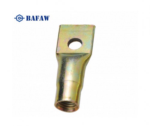
Fixing Insert - Flat End Lifting Socket - Fixing Socket With Cross Hole