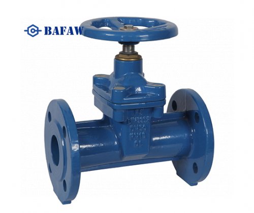
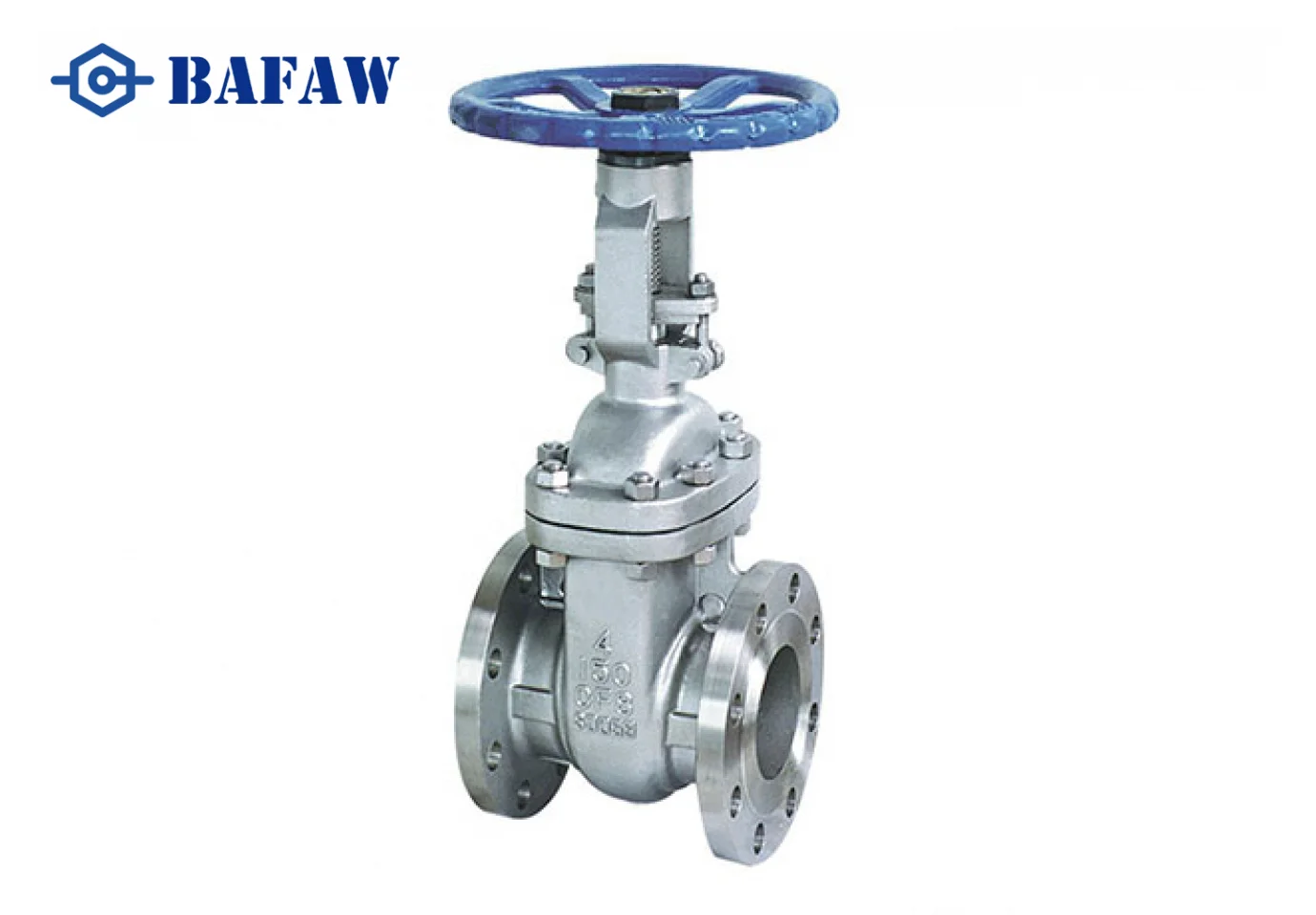
A gate valve is a type of valve used to control the flow of fluid in a pipeline. It operates by raising or lowering a gate (a wedge-shaped or parallel disc) to either allow or block the flow of the fluid. Gate valves are primarily designed for fully open or fully closed positions and are not generally used for flow regulation.
Key features of gate valves include:
Gate
The gate is the movable component of the valve that either blocks or permits fluid flow through the pipeline. It typically moves perpendicular to the direction of flow. There are three kinds of wedge discs used in gate valves:
Solid Wedge: A single solid piece of metal, suitable for almost all shutoff applications.
Flexible Wedge: A one-piece disc with perimeter cuts that adjust to the seating surfaces, accommodating slight misalignments.
Split Wedge: Consists of two pieces, ideal for handling corrosive liquids at normal temperatures.
Valve Body
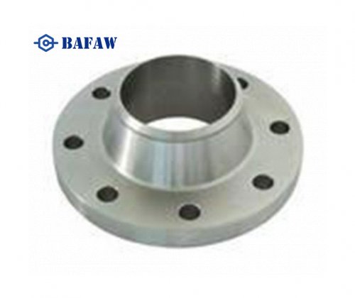
The valve body houses the gate and provides the passageway for the fluid. It is usually made of metal and is designed to withstand high pressures and temperatures. The body also attaches to the pipe system; its material classification often determines the valve category. End flanges can be forged, cast, or welded.
Bonnet
The bonnet is located on top of the valve body and guides the stem as it connects to the gate. There are several types of bonnets:
Screw-In Bonnet: Uses pressure to seal, suitable for low-pressure applications.
Union Bonnet: Allows for easier maintenance and cleaning.
Bolted Bonnet: Suitable for high-pressure applications, secured with bolts.
Pressure Seal Bonnet: Designed for extreme pressure applications exceeding 2250 psi.
Packing
Packing serves as the gasket, sealing the area between the stem and the body. Made of elastomeric material, packing is inserted into the stuffing box. When compressed by the gland, it forms a tight seal, preventing leaks.
Seat
Seats provide proper seating for the gate disc and are often made of elastomeric materials. Gate valves typically have two seats, located on each side of the gate. These seats can be integrally constructed with the valve body or come in the form of seat rings, which can be threaded, pressed into position, or seal welded to the body.
Actuator (Optional)
Some gate valves are manually operated using a wheel, handle, or lever to raise or lower the gate. Others may be equipped with actuators for automated operation, which can be pneumatic, electric, or hydraulic. These actuators are fixed with a nut and often have markings indicating the direction to open or close the valve.
Rising vs. Non-Rising Stem:
Gate valves may have either a rising or non-rising stem. In rising stem designs, the stem rises and lowers with the gate, providing a visual indication of the valve position.
For non-rising stem gate valves, determining if the valve is fully open or closed at first glance can be more challenging. Here are some tips to help:
Markers: Look for markers indicating the closing direction, either clockwise (cc) or anti-clockwise (acc). These can guide you in assessing the valve's position.
Position Indicators: Utilize position indicators, which are specialized devices mounted on the valve stem. These indicators provide a quick and clear reference for the valve's status.
Most gate valves close by turning clockwise. However, in certain regions, such as Australia or New Zealand, anti-clockwise closing gate valves are more common. Manufacturers often produce both versions to meet these local standards, ensuring compatibility with regional utilities.
In non-rising stem designs, the stem remains stationary while the gate moves.
Rising Stem Gate Valves:
The rotating stem rises as the valve is opened, allowing for a visual cue of the valve's position.
Disadvantages:
Space Requirements: Due to their bulky design, they require a greater amount of space when opened, as the spindle travels upwards.
Installation Limitations: They are not suitable for underground or buried installations.
Non-Rising Stem Gate Valves:
The threads on the stem remain inside the valve body. The valve gate travels up and down the stem threads once the valve stem is rotated.
Advantages:
Space Efficiency: Ideal for installations where space is limited, such as in pumping stations.
Underground Suitability: Suitable for buried service, allowing for versatile installation options.
A gate valve operates by raising or lowering a gate (a wedge-shaped or parallel disc) to control the flow of fluid through a pipeline.
Functions of the Stem in a Gate Valve
The stem in a gate valve plays a critical role by connecting the handwheel or actuator to the wedge disc. This connection is vital for controlling the opening and closing of the valve.
Key Functions:
Positioning the Disc: The stem directs the precise movement of the disc, ensuring it moves correctly up or down within the valve body.
Facilitating Movement: It acts as a bridge for the motion created by the handwheel or actuator, transmitting this force to the disc for efficient operation.
Types of Stems:
Rising Stem:
When the valve is opened, the stem visibly rises above the handwheel.
This design allows for easy visual indication of whether the valve is open or closed.
Non-Rising Stem:
The stem remains in a fixed position because it is threaded directly to the disc.
The disc moves along the threads when the valve is adjusted, meaning the stem does not extend outward.
Both designs have their unique mechanisms of function, but they share the fundamental role of ensuring the disc's movement aligns with the valve's operational requirements.
How Does a Non-Rising Stem Gate Valve Work?
In a non-rising stem gate valve, the threads on the stem are retained inside the valve body. As the stem rotates, the gate valve moves up and down along the stem threads. This design is particularly advantageous where installation space is limited (e.g., pump stations). In addition, non-rising stem gate valves are suitable for buried installation due to their compactness.
Detailed Design & Components
Gate valves are designed as full-port valves, meaning the valve port is the same size as the inner diameter of the connecting pipe. This design ensures that the fluid flow passes through without any obstructions, preventing pressure drops within the pipeline. This also allows for the cleaning of the pipe using a cleaning pig.
A resilient seated gate valve with a non-rising spindle consists of the following parts:
Wedge
Ductile iron valve body
Seating area
Stem (spindle)
Spindle bearing
Bonnet
Packing
The body is the largest element of the gate valve. Since the spindle remains in the valve body during rotation, it allows for a more economical bonnet construction. The valve bonnet is joined to the body with bolts, making it easier to clean and maintain. As the gate valve closes, the wedge travels down until it presses the valve seat, resulting in a complete shutoff. During opening, the wedge slides towards the upper part of the valve body.
Historical and Modern Enhancements
The basic construction of wedge gate valves has remained largely unchanged for the last 100 years. However, some elements of the gate valve have seen modifications aimed at increasing service life, improving sealing characteristics, and using superior quality materials and epoxy coatings for better corrosion protection. Modern gate valve bodies also feature a compact, sleek design, allowing installations in limited space conditions.
Here's how a gate valve works:
Fully Open Position
In the fully open position, the gate is raised fully into the valve body, allowing unrestricted flow of fluid through the pipeline. The fluid flows in a straight line with minimal resistance because there is no obstruction from the gate.
Closing the Valve
To close the valve, the operator rotates the valve handle, wheel, or actuator, depending on whether the valve is manual or automated. As the operator turns the handle, the stem attached to the gate begins to descend.

Gate Movement
As the stem descends, it lowers the gate into the flow path of the fluid. The gate gradually obstructs the flow of fluid until it is completely lowered into the valve body, effectively shutting off the flow.
Fully Closed Position
In the fully closed position, the gate forms a tight seal against the valve seat, preventing any further flow of fluid through the pipeline. The gate valve provides a complete shut-off, blocking the flow in both directions.
Opening the Valve
To open the valve, the operator rotates the valve handle or actuator in the opposite direction, causing the stem to rise. As the stem rises, it lifts the gate out of the flow path, allowing fluid to pass through the pipeline once again.

Gate valves are typically designed for either fully open or fully closed positions. They are not suited for throttling or regulating flow because partially opening the valve can cause erosion of the gate and seat due to the high-velocity flow of fluid. As a result, gate valves are often used in applications where the valve is primarily used for isolating sections of the pipeline or for on/off control rather than flow regulation.
When it comes to ensuring the safety and reliable operation of fluid pipelines, choosing the right valves is crucial, and gate valves stand out as an important option. Their simple yet effective operation makes them widely used across various industries, from chemical processing to energy sectors. however, selecting the appropriate gate valve involves understanding several key factors.
Industry Applications of Gate Valves
Gate valves find their place in a wide array of industries due to their robust design and functionality. Here are some specific applications:
Food Services: Used for the precise control of raw or processed ingredients in production lines.
Pharmaceutical Services: Essential for maintaining the purity of fluids in manufacturing processes.
Feedwater Applications: Integral in managing the flow of water in boiler systems.
Hydrocarbon Applications: Critical in the oil and gas industry for managing the flow of crude oil and natural gas.
Steam Applications: Employed in controlling steam flow in industrial heating processes.
Slurry Applications: Effective in handling abrasive slurries in mining and other heavy-duty applications.
Powder Product Applications: Used to control the flow of fine powders in manufacturing settings.
Petrochemical and Refinery: Reliable for managing various fluid processes in refineries.
What should you do if there is pressure while turning the gate valve?
pressure encountered while turning a gate valve:
Locate the Packing Nut: First, identify the packing nut situated on top of the gate valve body.
Loosen the Packing Nut: Carefully turn the packing nut counterclockwise. One full turn should suffice to reduce the pressure.
Open the Gate Valve: Proceed to turn the gate valve until it is fully open.
Retighten the Packing Nut: Once the gate valve is completely open, retighten the packing nut to its original position.
Important Note: Always ensure the packing nut is securely tightened after the gate valve has been fully opened to prevent leaks and maintain system integrity.
Material compatibility: Ensure that the valve material is compatible with the fluid it controls. Common materials include stainless steel, brass and iron, each suitable for different application scenarios.
Pressure and temperature ratings: Check the pressure and temperature ratings of the valve to match the operating conditions of the pipeline. This ensures that the valve can withstand the operating environment without failure.
Valve size and type: Select the correct size and type of gate valve for your specific application. This includes considering whether a rising stem valve or a non-rising stem valve is better suited to your needs.
End connections: Pay attention to the valve's end connections, which may include flanged, threaded or welded ends. The choice depends on the existing pipework set-up and ease of maintenance.
Operating Mechanisms: Choose manual, electric or pneumatic actuators depending on the level of control and automation required for your system.
For more information about gate valves, feel free to visit our company website.


