(0)
Products that you may be interested in
-

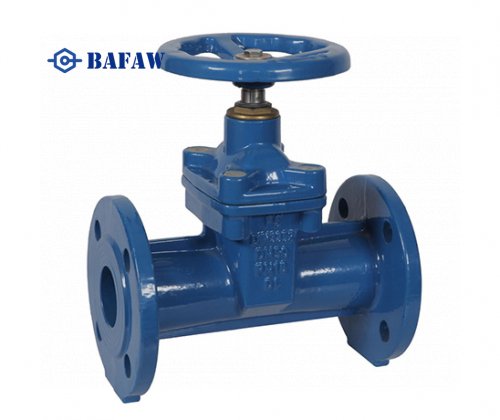
DIN3352 F5 Resilient Seat Cast iron Gate Valve
-
Ductile iron Swing Check Valve
-
OS&Y Gate Valve, API600 OS&Y Cast Steel Gate Valve
-
C509 AWWA C515 Cast iron Gate Valve
-
MSS SP-70 Metal-Seal Cast iron Gate Valve
-
MSS SP-71 Cast iron Swing Check Valve
-
Forged Steel Check Valve
-
2 Piece Threaded Steel Ball Valve


-
OEM Grey Iron And Ductile Iron Sand Casting Parts
-
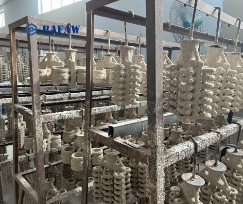
OEM Carbon Steel Precision Casting Part
-
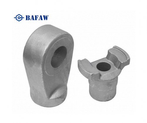
Ring Clutch - Precasting Concrete Lifting Ring Clutch
-
Lifting clutch
-
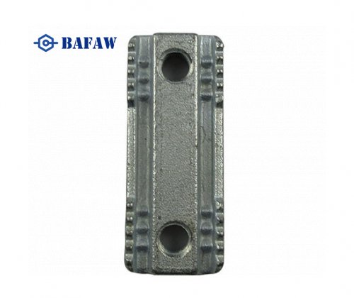
Double Clamp Nut
-
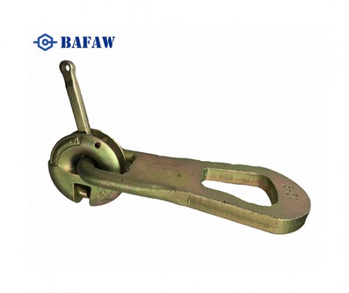
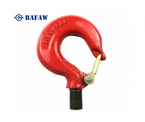
Carbon steel & Stainless steel Forging Metal Hook
-
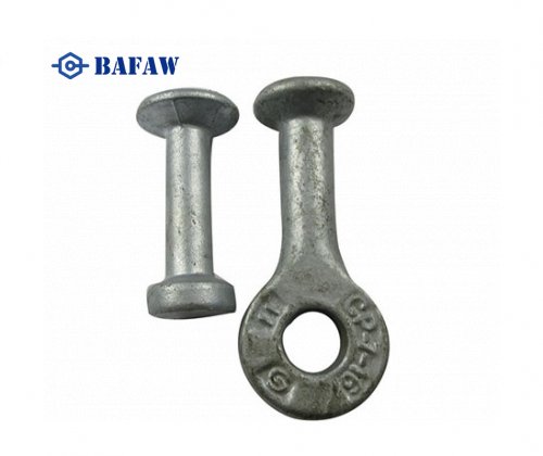
OEM High Quality Forging Parts With Clevis End Fitting
-
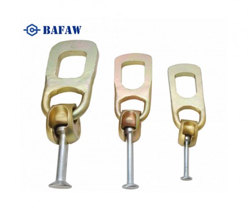
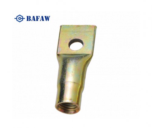
Fixing Insert - Flat End Lifting Socket - Fixing Socket With Cross Hole