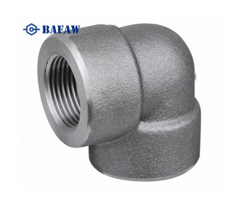
Material: Carbon Steel, Stainless Steel, Alloy Steel
Technical: Forged and pushing
Connection: Welding
Standard: ANSI, ASME,AP15L,DIN,JIS,BS,GB
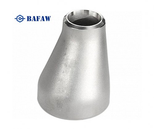
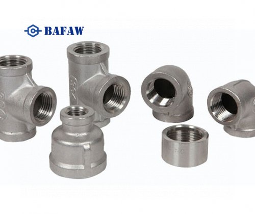
Type: 45°and 90°LR/SR Elbow, Reducers, Tee, Bends, Cap, Cross.
Wall Thickness: SCH5-SCH160 XS XXS STD
Surface: Black Paint/Rust-proof Oil/Hot Dipped Galvanized
Angles: 30/45/60/90/180°
Size: 1/2”-80”/DN15-DN2000
Certificate: ISO -9001:2000, API, CCS
Application: Chemical Industry, Petroleum Industry, Construction Industry and Other
Inspection: Factory In-House Check or The Third Party Inspection
Packing: Plywood Pallets/ Wooden Case Or As Per your Specification
Pipe Size | All Fittings | 90 & 45 Elbows and Tees | Reducers and Lap Joint Stub ends | Caps | ||||||||
Outside Diameter at Bevel, D (1) | Inside Diameter at End (1) | Wall Thicknesst | Center-to-End Dimensions A,B,C,M | Overall Length,F,H | ||||||||
Overall Length,E | ||||||||||||
IN | MM | IN | MM | IN | MM | IN | MM | IN | MM | |||
½ ~ 2½ | +0.06 | +1.6 | ±0.03 | ±0.8 | Not Less Than 87.5% of Nominal Thickness | ±0.06 | ±2 | ±0.06 | ±2 | ±0.12 | ±3 | |
-0.03 | -0.8 | |||||||||||
3 ~ 2½ | ±0.06 | ±1.6 | ±0.06 | ±1.6 | ||||||||
4 | ||||||||||||
5 ~ 8 | +0.09 | +2.4 | ±0.25 | ±6 | ||||||||
-0.06 | -1.6 | |||||||||||
10 ~ 18 | +0.16 | +4.0 | ±0.12 | ±3.2 | ±0.09 | ±0.09 | ||||||
-0.12 | -3.2 | |||||||||||
20 ~ 24 | +0.25 -0.19 | +6.4 -4.8 | ±0.19 | ±4.8 | ||||||||
26 ~ 30 | ±0.12 | ±3 | ±0.19 | ±5 | ±0.38 | ±10 | ||||||
32 ~ 48 | ±0.19 | ±5 |
Pipe Size | Lap Joint Stub Ends (2) | 180 Return Bends | ||||||||||
Outside Diameter of Lap, G | Lap Thickness | Fillet Radius of Lap, R | Center-to-Center Dimension, O | Back-to- Face Dimension, K | Alignment of Ends, U | |||||||
IN | MM | IN | MM | IN | MM | IN | MM | IN | MM | IN | MM | |
½ ~ 2½ | +0 -0.03 | +0 -1 | +0.06 -0 | +1.6 -0 | +0 -0.03 | +0 -1 | ±0.25 | ±6 | ±0.25 | ±6 | ±0.03 | ±1 |
3 ~ 2½ | ||||||||||||
4 | +0 -0.06 | +0 -2 | ||||||||||
5 ~ 8 | ||||||||||||
10 ~ 18 | +0 -0.06 | +0 -2 | +0.12 -0 | +3.2 -0 | ±0.38 | ±10 | ±0.06 | ±2 | ||||
20 ~ 24 |
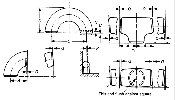
Pipe Size | Off Angle, Q | Off Plane, P | ||
IN | MM | IN | MM | |
½ ~ 4 | ± 0.03 | ± 1 | ± 0.06 | ± 2 |
5 ~ 8 | ± 0.06 | ± 2 | ± 0.12 | ± 4 |
10 ~ 12 | ± 0.09 | ± 0.19 | ± 5 | |
14 ~ 16 | ± 3 | ± 0.25 | ± 6 | |
18 ~ 24 | ± 0.12 | ± 4 | ± 0.38 | ± 10 |
26 ~ 30 | ± 0.19 | ± 5 | ||
32 ~ 42 | ± 0.50 | ± 13 | ||
44 ~ 48 | ± 0.75 | ± 19 |
NOTES:
(1)Out-of-round is the sum of absolute values of plus and minus tolerances.
(2)Outside diameter of barrel see the table on page 15.
Advantages of concentric reducers include providing a smooth flow transition, helping to avoid cavitation, and maintaining symmetry in the reduction of pipe diameter. Concentric reducers are not suitable for use in horizontal liquid piping to avoid the formation of cavitation pockets as compared to eccentric reducers. When selecting concentric reducers, consider the size of the pipe being connected, material compatibility with the fluid being communicated, pressure requirements, and particular application needs.
Concentric reducers are fittings used to connect pipes of different sizes and are developed to feature a progressive shift from larger to smaller diameters, preserving a common centerline. These fittings are commonly used in piping systems where they are required in vertical flow applications or as reducers in horizontal layouts.
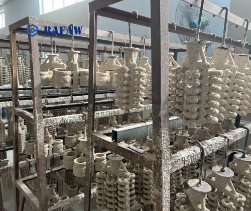
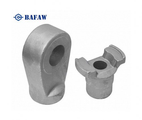
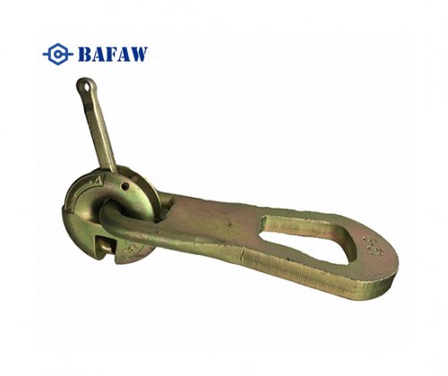
Comprehensive product customization
Secondary Quality Testing Before Leaving The Factory
Increased Capacity Based on Customer Demand - Fast Delivery
Provide a Customized Service Process That Dits The Needs of Our Customer